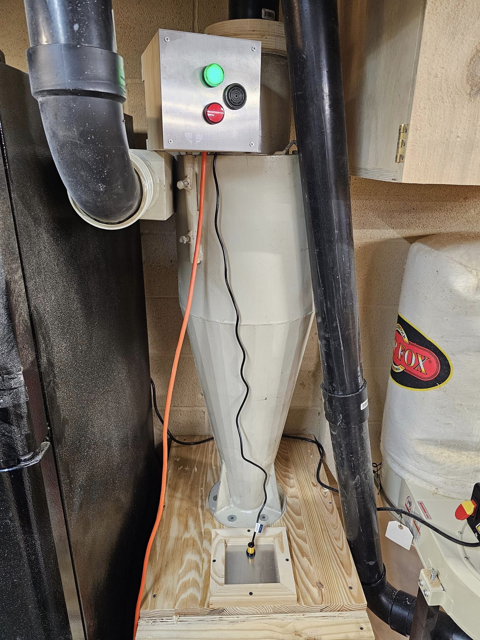
With a bit of creativity and roughly $40 for the parts my dust collector will now let me know when my bin is full in the separator.
The parts (see definitions below) All part #s are from Amazon
24 volt power supply
PNP NO diffusion photoelectric sensor
24 volt coil relay (has 1 NO output and 1 NC)
Red/Green 24 volt LED
24 volt buzzer
6 x 6 aluminum plates (are from amazon)
PNP means Positive/Negative/Positive also known as a sourcing sensor. I used a Taiss photoelectric Sensor (6-36VDC E3F-DS30P1).
The power supply I used was 24 volt output and 120/208/240 input for DIN rail mounting. I used the 120 volt option and it is auto-sensing. The output provided up to two amps which is way more than is needed for this project.
NO means normally open
NC means normally closed
When the relay is powered off the a circuit is created between (11) and (12). When the relay is powered on then that circuit is opened and a circuit is created between (11) and (14). So NC becomes open and NO becomes closed.
I also chose a ultra-thin DIN mount 24 volt solid state relay similar to (ASI328002)
For LED lights I used (https://www.amazon.com/dp/B01N94QZST?psc=1)
The buzzer I already had but this would suffice. (https://www.amazon.com/BNYZWOT-Continuous…/dp/B07VT6577Q)
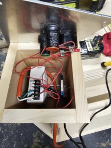
As for the wiring
Power supply 120 volt in (Line, Neutral, Ground) to the provided marked terminals. 24 volt out is marked Positive and Negative.
Relay
Connect A1 of relay to Black wire of photosensor (+)
Connect A2 of relay to 24 volt power supply (-)
Photosensor
Connect Brown wire to 24 volt power supply (+)
Connect Blue wire to 24 volt power supply (-)
As stated above Black wire goes to A1 of relay (+)
Connect a short wire from terminal marked (+13)11 to A2 of the relay (-)
Now the fun part between Normally open and Normally closed.
Connect a wire from the negative side of the green light to terminal (12) on the relay.
Connect a wire from the negative side of the red light to terminal (14) on the relay. Run a short wire from the negative side of the red light to the negative terminal of the buzzer.
Connect a wire from the Positive (+) output of the 24 volt power supply to the positive side of the green light. Connect a short wire from the Positive side of the green light to the positive side of the red light. Connect a short wire from the positive side of the red light to the positive side of the buzzer.
Ultimately that is what it takes to make this work. The photoelectric sensor is referred to as a diffusion sensor. What this means is the laser transmitter and receiver is built in to the sensor and uses reflection from objects to detect its own light. You can adjust this sensor to detect objects from roughly 3 inches to 18 inches away. When the sensor does not detect an object the green light is on. When an object comes into range the green light turns off and the red light and buzzer turn on.
I hope you find this helpful
Steve